


UL924 emergency
load controller
Line Voltage
Series Downloads
Instructions
Overview
During normal operation, SENSORWORX digital emergency load controllers switch on/off emergency power to connected lighting as directed by digitally linked sensors, photocells, and wall stations. If it senses the loss of normal power feeding the load controllers on the same 18/3 wired dataline, it will override its relay closed within 5 seconds and remain in that state until normal power is restored. The unit’s 0-10V dimming option greatly simplifies applications where dimming control from multiple switch locations is required. Upon loss of normal power, this dimming output will be held at full bright. When power is restored, the unit will be allowed to return to a dimmed level. This SENSORWORX digital load controller is rated to switch 120-277 VAC loads up to 16A and utilizes a powerful microprocessor to optimize its switch timing, ensuring long relay life even when controlling high-inrush LED lighting.
The SENSORWORX digital suite of products communicate over a topology-free, 3-wire data line connection. Data line wiring uses common 18/3 cable & wire nuts, thus eliminating the issues that plague CAT-5 based systems. These individually addressable load controllers are digitally zoned together with wall stations and sensors via one of three methods. The first is the out-of-the-box single zone default configuration, the second (for multi-zone applications) is by using a push-button pairing sequence, and the third is via the SENSORWORX mobile application (also requires SWD-940 Advanced Load Controller). Once paired, a digital control zone can be highly configured with several operating modes, dimming settings, and photocell parameters.
As with all SENSORWORX products, these devices are easy to install and incorporate mechanical features which reduce contractor labor time. An elongated chase nipple with snaps for quick mounting and an optional snap-on low voltage wire chamber make for a hassle free contractor experience. All SENSORWORX products are proudly made in the USA.

Applications
Using the SENSORWORX DIGITAL system, code compliance is a breeze. Installation only require a 3-wire inter-connection between SWD-900 series load controllers, SWD-200/400 series sensors, and SWD-800 series switches. All devices are digitally linked/paired via the same push-to-pair method as the SENSORWORX WIRELESS system or via the App.
The SENSORWORX DIGITAL Emergency Load controller (SWD-900-EM-D1/D2) is certified to UL-924 for controlling circuits fed with emergency backed up power. If there is a loss in normal power it will no longer sense +VDC on its red class 2 input wire that is powered by other load controllers connected to normal power. As a result, it will override its internal relay closed (on) and make its dimming output (if present) full bright within 5 seconds. During the emergency state it will not be controlled by any other connected devices and shall stay on until normal power is restored.
Applications can be easily deployed to meet the requirements such as, Occupancy, Vacancy, Partial On, and Partial Off. In addition, Daylight Harvesting and multi-way dimming/switching.
- Classrooms
- Open Areas
- Conference Rooms
- Hallways
- Small Offices
- Copy Rooms
- Private Restrooms
- Break Rooms

Features / Digital UL924 emergency load controller
-
Digitally Addressable – Creates Sophisticated Control Zones of Sensors, Photocells, & Wall Stations
-
Automatically Pairs to all Devices on a Dataline – Provides Instant Wiring Validation
-
3-Wire Topology – Free Digital Architecture – Enables Flexible Installation
-
Connects with 18/3 Cable & Wire Nuts – Eliminates Issues that Plague CAT-5 Systems
-
UL 924 Emergency Operation
-
Switches Up to 16A Line Voltage Load (120-277 VAC)
-
Electronically Timed Switching (i.e. Zero Crossing) Ensures Long Relay Life
-
Integrated Emergency Test Button
-
Plenum Rated (UL 2043)

Specifications
Physical
SIZE / WEIGHT / COLOR
3.00” H x 2.25” W x 1.88” D(7.62 cm x 5.72 cm x 4.78 cm)
6.00 oz.
Black w/ Red EM Label
MOUNTING
1/2” Knockout
TEST BUTTON
LED STATUS INDICATOR
Bi-color White & Blue
Operation
OPERATING MODES
Occupancy & Vacancy
Partial On/Off
Daylight Harvesting
On/Off/Inhibit Photocell
Ignore Occupancy/Switching/Dimming
TIME DELAY OPTIONS
1, 5, 10, 15, 20, 30 min.
1,2,4,8 hr.
Custom (via Mobile App)
Electrical
OPERATING VOLTAGE
120-277 VAC (-900 Models)
120/347 VAC (-903 Models),
Single Phase, 50/60 Hz
CLASS 2 EM SIGNAL INPUT
15 VDC
LOAD RATINGS
(relays use zero-cross switching)
16A @ 120-277 VAC or
20A @120/347 VAC General Purpose, Tungsten, Magnetic Ballast
16A @ 120-277 VAC & 120/347 VAC -Electronic Ballast, LED Driver
DIMMING LOAD
(Models with -D1/D2 option only)
50mA, (0-10 VDC ballasts or drivers compliant with IEC 60929 Annex E.2)
MOTOR LOAD
1 HP
ESD IMMUNITY
Tested to withstand electrostatic discharge without damage or memory loss
Security
Digitally encrypted communications.
Digital Data Line
WIRES (3)
+VDC EM Input, Digital Data,
Common
18/3 Cable Recommended
LENGTH
1000 ft – Point-to-Point4000 ft – Total Bus Length
PROTOCOL
Proprietary SENSORWORX
ZONE CONFIG. METHODS
Out-of-the-box (single zone only)
Push-Button (required for multi-zone)
Mobile App (requires a SWD-940)
Environmental
OPERATING TEMP
32°F to 122°F (Standard
0°C to 50°C (Standard
-40° F/C (with -HE Option)
RELATIVE HUMIDITY
0-95% Non-Condensing
Indoor Use Only
Code Compliance
UL-924 Certified Device
Load controllers can be used to meet ASHRAE 90.1, IECC, & Title 24 energy code requirements
Wiring
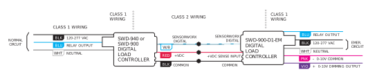
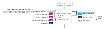
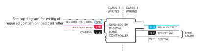
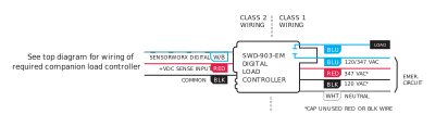
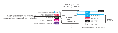
To enable Emergency functionality, a SWD-900/940/970 Series load controller that is powered via normal power must provide a +VDC signal connection to the -EM load controller powered from Emergency power.
SWD-900-D1-EM
SWD-900-D2-EM
SWD-900-EM
SWD-903-EM
SWD-903-D2-EM
Installation

Digital Zone Configuration
A. Out-of-the-Box (single zone only)
B. Push-Button Pairing (required for multi-zone)
C. Mobile App Pairing (requires a SWD-940/970 on digital data line)
A. OUT-OF-THE-BOX FUNCTIONALITY
By default, digital load controllers listen to all devices connected via the data line. This enables installers to immediately verify all device wiring, and provides instant control of single zone rooms. Default listening is cancelled once the first device is paired via method below.
B. PUSH-BUTTON PAIRING (see diagram below)
Step 1. Enter pairing mode by holding down the load controller’s button for 3 seconds until the LED starts alternating white then blue.
Step 2. At a sensor or wall station device on the same data line, hold down the programming button for 3 seconds until the LED starts alternating white then blue. Upon release the remote device will be paired to the load controller. The lights will toggle once as confirmation.
Step 3. Repeat step 2 to link additional sensors or remote devices.
Step 4. When all devices have been linked, exit pairing mode on the load controller by pressing its button 1 time. Exiting will also occur automatically after 15 minutes of no new devices being linked.
Note 1: When in pairing mode, the alternating LED colors on the load controller will periodically pause and blink out the total number of linked devices. There will be no blinks during the pause until the first device is linked via the push-button (or mobile app.) pairing process.
Note 2: Once the first remote device has been paired to the load controller it will stop listening to all non-paired devices on the data line.
C. MOBILE APP PAIRING
Note: Requires a SWD-940 Advanced Load Controller be on the same data line as the sensor.

Ordering Info
EXAMPLE MODEL # SWD-900-D2-EM
| MODEL | DESCRIPTION | OPTIONS | ||
|---|---|---|---|---|
| SWD–900-EM | Digital UL-924 Emergency Load Controller, 120-277 VAC | Blank | Blank | |
| SWD-900-D1-EM | Digital UL-924 Emergency Load Controller, 120-277 VAC, w/ 0-10V Dimming (Class 1) | Low Temp. / High Humidity | –HE | |
| SWD-900-D2-EM | Digital UL-924 Emergency Load Controller, 120-277 VAC,w/ 0-10V Dimming (Class 2) | |||
| SWD-903-EM | Digital UL-924 Emergency Load Controller, 120/347 VAC | |||
| SWD-903-D2-EM | Digital UL-924 Emergency Load Controller, 120/347 VAC, w/ 0-10V Dimming (Class 2) |
| ACCESSORY | DESCRIPTION |
|---|---|
| SWX-999 | Snap-On Low Voltage Wiring Chamber |


