


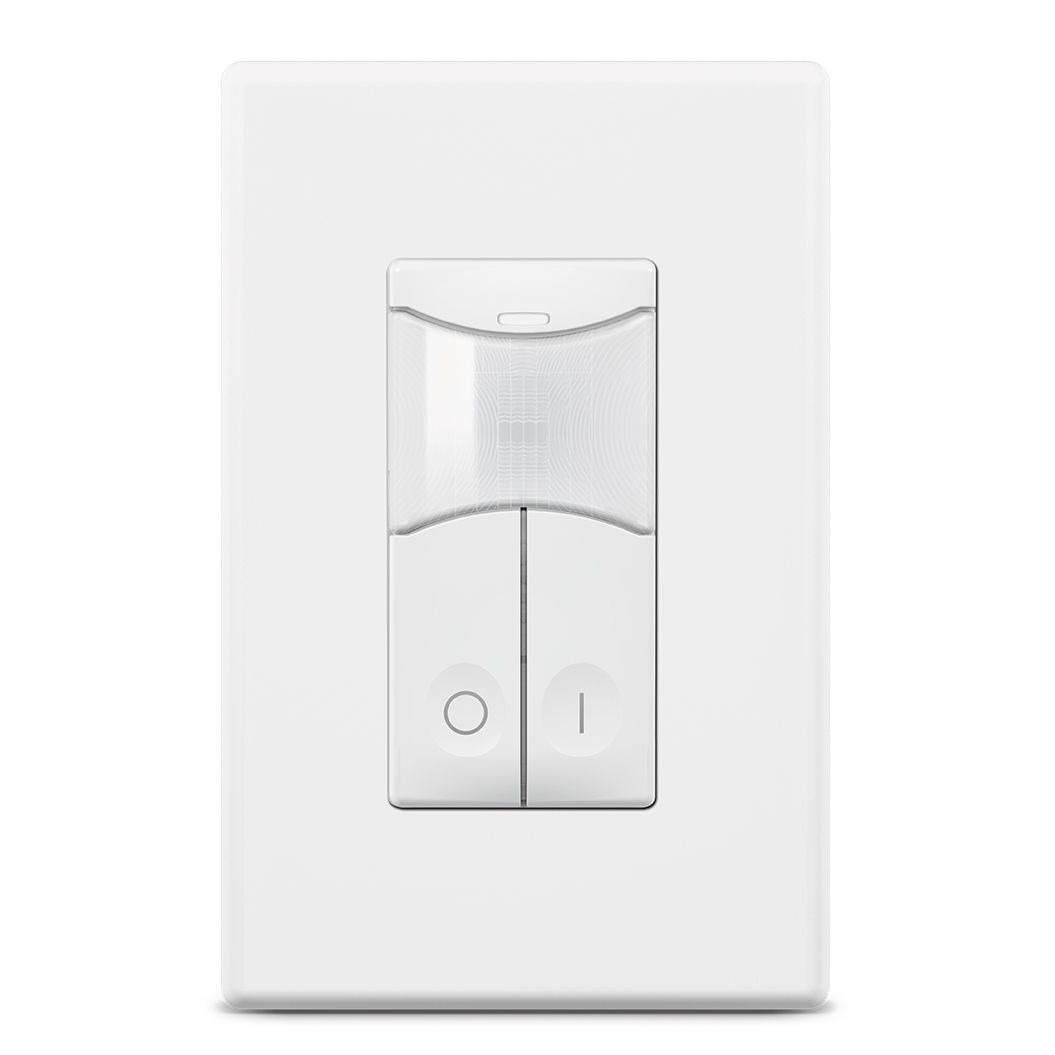
Wall Switch Occupancy Sensor
SWD-100 SERIES
Series Downloads
Instructions
Overview
SENSORWORX digital wall switch occupancy sensors detect movement in the infrared energy that radiates from occupants as they move within the device’s field-of-view. Once occupancy is identified, the sensor signals a connected load controller to switch on the connected lighting. Units can also be configured to operate in Vacancy Mode (e.g. require lights be manually switched on) via the paired load controller. Once lights are on and if equipped with passive dual technology (PIR/Acoustic), the unit’s microphone is enabled to further enhance detection. An internal timer is set to keep lights on during brief period of inactivity, and is reset every time occupancy is signaled by either the passive infrared or acoustic detection techniques. This two button unit enables users to switch lighting on/off via a single button press, or to raise/lower dimmable lighting by pressing and holding the buttons..
The SENSORWORX digital suite of products communicate over a topology-free, 3-wire data line connection. Wiring uses common 18/3 cable & wire nuts, thus eliminating the issues that plague CAT-5 based systems. These individually addressable wall switch sensors are digitally zoned together with load controllers and sensors via one of three methods. The first is the out-of-the-box single zone default configuration, the second (for multi-zone applications) uses a push-button pairing sequence, and the third is via the SENSORWORX mobile application (also requires SWD-940/970 Advanced Load Controller). Once paired, a digital control zone can be highly configured with several operating modes, dimming settings, and photocell parameters.

Applications
Adding a digital wall switch occupancy sensor to a room controlled by one or two SENSORWORX digital load controllers (SWD-900/940/970) enables code compliant partial on or vacancy (manual on) operation for the space.
A Passive Infrared (PIR) only sensor is sufficient for spaces where line of site is maintained and occupants are periodically moving (e.g. copy rooms, storage rooms). Dual technology sensors are necessary where occupants may be partially blocked from the sensor’s direct view or where they may be stationary (e.g. private offices or restrooms with stalls).
Additional wall switch, ceiling, or wide view sensors can be paired together for large or irregularly shaped spaces. Multiple units or remote wall stations can also be combined to provide user control from multiple locations (3-way & multi-way). This can be useful in meeting rooms with multiple entrances.
- Private Restrooms
- Copy Rooms
- Restrooms with Stalls
- Small Meeting Rooms
- Small Offices
- Vestibules
- Storage Rooms
- Break Rooms
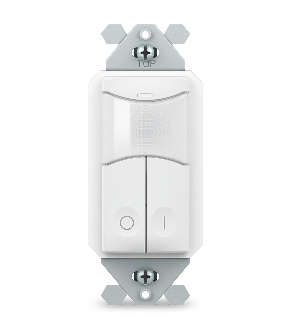
Features / Wall Switch Occupancy Sensor
- Wall-To-Wall Passive Infrared Small Motion Detection
- Passive Acoustic Detection (Optional) – Prevents False Offs from Lack of Motion
- 100% Passive Detection Methods – No Interference Potential from External Devices
- Pairs with SENSORWORX Digital Load Controllers
- On/Off and Raise/Lower Control from Single 2-Button Model
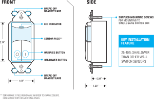
- Requires < 1” Depth in Wallbox – 25-40% Shallower than other Wall Sensors
- Decorator Style Fits Common Wall Plates (not included)
-
Swappable Faces with 6 Color Options
-
Matches Styling of other SENSORWORX Wired & Wireless Wall Stations
-
Enables Multiway Switching & Dimming (e.g., 3-way, 4-way)
-
3-Wire Topology-Free Digital Architecture Enables Quick Installation
-
Connects with 18/3 Cable & Wire Nuts – Eliminates Issues that Plague CAT-5 Based Systems

Specifications
Physical
SIZE
2.74”H x 1.68”W x 1.39”D
(6.96 x 4.27 x 3.53 cm)
Fits decorator switch plate opening
2.5 oz
Single gang switch box
LED INDICATION
Motion Detection
Pairing
Comm. Error
Active User Dimming
Operation
OPERATING MODES
Configured at paired load controller(s)
Occupancy: Auto-On, Partial On/Off, Manual On ( Vacancy), etc.
TEST MODES
Button press toggles all paired load controllers
Coverage test mode shortens time delay and isolates sensor.
TIME DELAY OPTIONS
Configured at paired load controller(s)
1, 5, 10, 15, 20, 30 min.
1,2,4,8 hr.
Custom (via Mobile App)
Electrical
OPERATING VOLTAGE
15 VDC
CURRENT DRAW
8 mA (PIR models)
8.5 mA (PIR + Photocell models)
9 mA (Dual Tech models)
9.5 mA (Dual Tech + Photocell models)
Digital Data Line
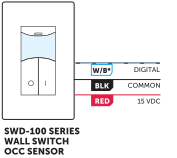
WIRES (3)
Power, Common, Digital Data
18/3 Cable Recommended
LENGTH
1000 ft – Point-to-Point
4000 ft – Total Bus Length
PROTOCOL
Proprietary SENSORWORX
ZONE CONFIG. METHODS
Out-of-the-box (single zone only)
Push-Button (required for multi-zone)
Mobile App (requires a SWD-940/970)
Security
Digitally encrypted communications.
Environmental
OPERATING TEMP
32°F to 122°F – Standard
0°C to 50°C – Standard
-40° F/C (with -HE Option)
RELATIVE HUMIDITY
0-95% Non-Condensing,
Indoor Use Only
CODE COMPLIANCE
These switches can be used to meet ASHRAE 90.1, IECC, & Title 24 energy code requirements.
Digital Zone Configuration
A. Out-of-the-Box (single zone only)
B. Push-Button Pairing (required for multi-zone)
C. Mobile App Pairing (requires a SWD-940/970 on digital data line)
A. OUT-OF-THE-BOX FUNCTIONALITY
By default, digital load controllers listen to all devices connected via the data line. This enables installers to immediately verify all device wiring, and provides instant control of single zone rooms. Default listening is cancelled once 1st device is paired via method below.
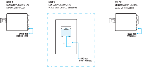
B. PUSH-BUTTON PAIRING (SEE DIAGRAM BELOW)
Step 1. Enter pairing mode by holding down the button on the load controller to be linked for 3 seconds until the LED starts alternating white then blue.
Step 2. At the wall switch sensor, hold down the ON button (see diagram below) until the LED starts alternating white then blue. Upon release the load controller will be paired (i.e. linked) to the wall switch sensor. The lights will toggle once as confirmation. (Note: this unit’s default setting has dimming capabilities enabled and will require an extended 8 sec. press for pairing).
Step 3. Repeat step 2 to link additional switches/dimmers (or sensors).
Step 4. When all devices have been linked, exit pairing mode on the load controller by pressing its button 1 time. Exiting will also occur automatically after 15 minutes of no new devices being linked.
Note 1: When in pairing mode, the alternating LED colors on the load controller will periodically pause and blink out the total number of linked devices. There will be no blinks during the pause until the first device is linked via the push-button (or mobile app.) pairing process.
Note 2: Once the first remote device has been paired to the load controller it will stop listening to all non-paired devices on the data line.
C. MOBILE APP PAIRING
Note: Requires a SWD-940/970 Advanced Load Controller be on the same data line as the wall switch sensor.
Operation Notes
-
The unit’s LED will light blue when a button is pressed.
-
When used with a dimming load controller, the ON button can be pressed and held to raise the lights level and the OFF button can be held to dim the lights down.
-
When dimming the device, the unit’s LED will rapidly flash white when the highest or lowest dim state has been reached.
-
This unit’s default setting has dimming capabilities enabled and will require an extended press for pairing, detailed in the Digital Zone Configuration section.
-
Manual adjustment of a control zone’s operational settings and time delays is done via the connected load controller device’s push-button. If paired to an advanced load controller, configuration can also be completed via the SENSORWORX Config Mobile App.
-
Disabling/enabling of the unit’s dimming adjustment functionality is the only configuration change made at the wall switch sensor device.
Wiring
-
3-wire digital data line (class 2)
-
Topology free
-
18/3 wire recommended (18 Gauge, 3 Conductor)
-
Example common class 2 wire types
– AV / Thermostat Cable
– Belden 8463MN (Non-Plenum, unshielded, 18/3)
– Belden 8770 (Shield, 18/3)
– Belden 82418 (Plenum & Shield, 18/4)
Installation
-
Designed to mount in 1-gang wall box with 3.28” hole spacing.
-
Units can also share multiple gang wall boxes with other devices.
-
Faces and buttons can be replaced without uninstalling the device to change colors.
Ordering Info
EXAMPLE MODEL # SWD-101-WH
| PRODUCT | DESCRIPTION | COLOR* | OPTIONS | |||||
|---|---|---|---|---|---|---|---|---|
| SWD– | 101 | Digital Occupancy Wall Sensor w/ On/Of/Raise/Lower Dimming Control , PIR | White | –WH | Blank | Blank | ||
| 111 | Digital Occupancy Wall Sensor w/ On/Of/Raise/Lower Dimming Control , PIR + Photocell | Ivory | –IV | Low Temp / High Humidity | –HE | |||
| 121 | Digital Occupancy Wall Sensor w/ On/Of/Raise/Lower Dimming Control , Dual Tech | Light Almond | –LA | 10 Count Pack | -J10 | |||
| 131 | Digital Occupancy Wall Sensor w/ On/Of/Raise/Lower Dimming Control , Dual Tech + Photocell | Gray | –GY | |||||
| Red | –RD | |||||||
| Black | –BK |
* WAll plate(s) not included
| ACCESSORY PART # | DESCRIPTION | COLOR | ||
|---|---|---|---|---|
| SWX–199 | Single Gang Wall Plate | White | –WH | |
| SWX–192-FACE | Color Change Kit for SWD-101 | Ivory | –IV | |
| Black | –BK | |||
| Light Almond | –LA | |||
| Gray | –GY | |||
| Red | –RD |


